Crushing Equipment – Structure and Main Components of the Hammer Crusher
Structure and Main Components
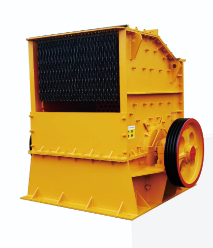
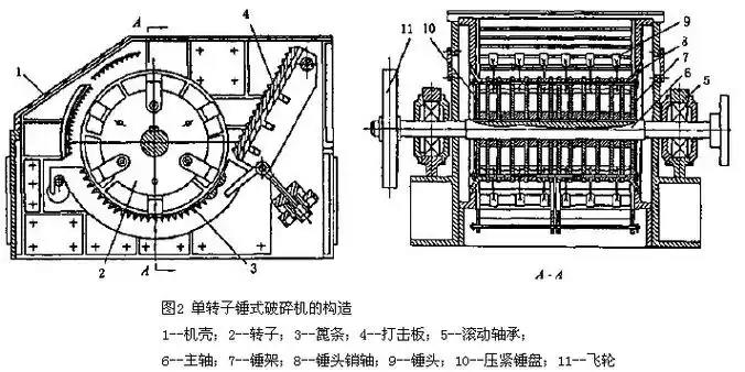
The diagram illustrates a 1600 mm × 1600 mm single-rotor, non-reversible, multi-row, articulated-hammer hammer crusher produced in China. It is composed of a drive system, rotor, grate screen, y marco. The motor drives the main shaft (8) directly via an elastic coupling (1), with a shaft speed of 600 r/min. The main shaft is mounted in bearing housings on both sides of the frame by spherical roller bearings (2), lubricated with dry grease. To minimize hammer speed loss when crushing large lumps and to reduce motor peak load, a flywheel (11) is installed at one end of the main shaft.
The crusher frame is a box-type welded structure made of steel plates. It is divided along the rotor centerline into an upper frame (16) and a lower frame (15), bolted together. The upper frame houses the feed inlet, and the inner wall is lined with manganese-steel plates. The lower frame is directly mounted on a concrete foundation. For maintenance, adjustment, and grate replacement, inspection openings are provided at the front and rear of the lower frame. Additional symmetrical inspection openings on both sidewalls facilitate hammer replacement.
The rotor consists of the main shaft (8), discs (10), hammers (6), and related parts. Eleven discs are rigidly connected to the shaft with keys, with spacers (9) placed between them and secured by locknuts at both ends to prevent axial displacement. Hammer pins (4) pass through all discs and suspend hammers in four rows between the discs, secured with locknuts. Each pin holds 10 hammers, totaling 40. A second set of pin holes is provided on the discs; when the hammers are worn down by 20 mm, they can be relocated to the second set of holes for continued use.
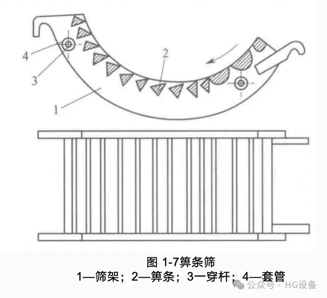
Below the rotor is a grate screen composed of an arc-shaped frame and grate bars. The grate frame is suspended on cross-shafts, which are hung outside the frame with eye bolts. Adjusting the position of the bolts changes the clearance between hammer tips and grate bars (within 20 mm). The 1600 mm × 1600 mm single-rotor crusher has a production capacity of 300 T/H, a maximum feed size of 350 mm, product size below 25 mm, rotor speed of 585 r/min, and a motor power of 480 KW.
The hammer crusher’s main components include hammers, rotor, grate screen, liner plates, y marco. Among these, hammers and grates are the most frequently replaced and play the primary roles in crushing.
(1) Hammer
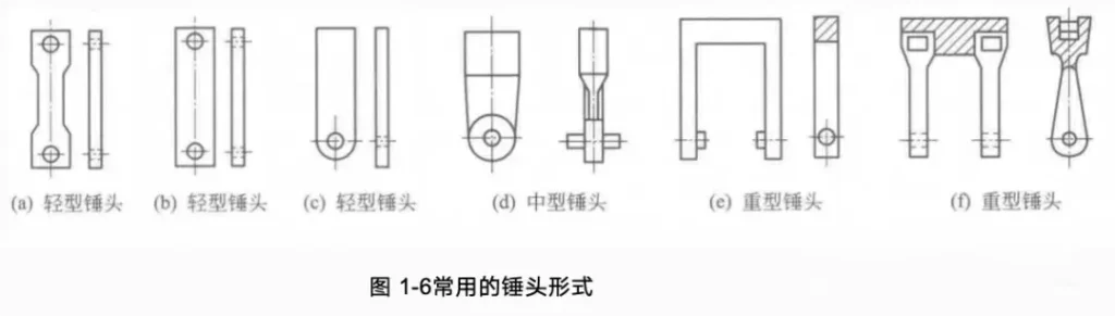
The hammer is the crusher’s principal working part, with wear resistance as its key quality indicator. Improving hammer wear resistance reduces downtime for repairs, increases utilization, and lowers maintenance costs. At a given rotor speed, heavier hammers have greater kinetic energy and are better suited for breaking large or hard materials. Effective hammer mass must not only deliver sufficient impact but also resist deflection; otherwise, capacity drops and energy consumption rises.
- Light hammers (3.5–15 kg): suitable for soft materials with 100–200 mm feed size. Some designs allow up to 4 reuses by rotating ends, others only twice.
- Medium hammers (30–60 kg): heavier with more offset centers, used for medium-hard materials; can be reused twice.
- Heavy hammers (50–120 kg): for large, hard materials; reusable twice after wear.
(2) Rotor
The rotor consists of the main shaft, discs (or polygonal hammer carriers), and hammers. The shaft, which bears impact forces, must have high strength and toughness, often forged from 37SiMn2MoV alloy steel. Typical dimensions: maximum shaft diameter 280 mm, 200 mm at bearings. The hammer carrier (disc) is keyed to the shaft or, in some designs, mounted on a square shaft without keys.
Discs are subject to wear due to contact with material and therefore require wear resistance and weldability. Local wear can be repaired by surfacing. Since the rotor operates at high speed, static and dynamic balancing is necessary after installing new hammers or designing a new rotor.
(3) Grate Screen
The grate screen consists of grate bars, frame, and clamping plates. The gap between bars widens outward, allowing crushed material to discharge quickly. For better crushing and discharge, the bar surfaces are inclined downward in the rotor’s rotation direction.
The 1600 mm × 1600 mm crusher uses two grate segments. At the feed end, larger rectangular bars are installed to withstand the heavy impact of large lumps.
- Triangular section bars: wide gaps, less prone to clogging, but lower durability, prone to breakage and wear enlargement, leading to coarser product.
- Trapezoidal section bars: stronger and more durable, gaps maintain size, but prone to clogging with moist materials.
Bars are commonly cast from manganese steel.
(4) Safety Device
Metallic inclusions pose a severe hazard to crushers. To prevent accidents, hammer crushers are fitted with safety devices. On the main shaft (1), a safety bronze sleeve (2) is installed, with the pulley (3) mounted on it and connected by a shear pin (4). When metal enters or overload occurs, the shear pin breaks, protecting the crusher.
Performance Features and Applications
Hammer crushers offer:
- High production capacity
- Large crushing ratio (typically 10–25, up to 50)
- Low power consumption
- Simple, compact structure
- Low investment and easy operation
However, disadvantages include:
- High hammer and grate wear when processing hard materials
- Significant metal consumption
- Longer maintenance times
- Need for uniform feeding
- Reduced capacity or stoppage when handling moist or sticky materials (feed moisture ≤ 10% recommended)
Product size depends on rotor speed and grate gap. Slow-speed crushers produce coarser products, with nearly linear particle-size curves. Narrower grate gaps yield finer product but reduce throughput. High-speed crushers produce finer products, capable of both medium and fine crushing.